

Views: 0 Author: Site Editor Publish Time: 2026-10-19 Origin: Site


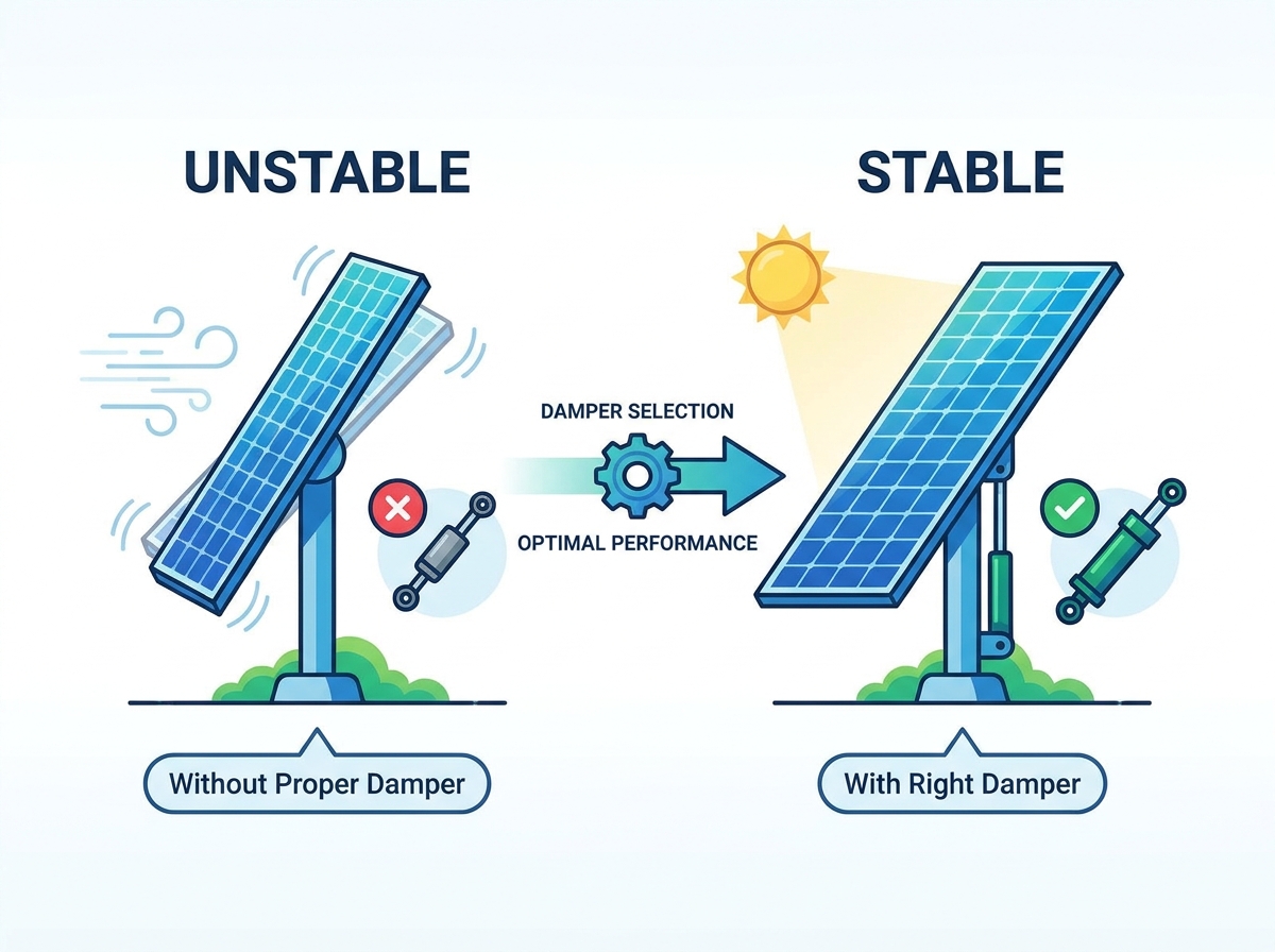
A damper helps control wind-induced movement in a single-axis solar tracker. It dissipates mechanical energy and can reduce vibration under suitable operating conditions. Choosing the right damper requires more than checking its rated force. Engineers must also consider the tracker design, force-velocity characteristics, stroke length, mounting geometry, site climate, and maintenance requirements.
An unsuitable damper may restrict normal tracking movement or fail to provide the required damping performance. The selection process should therefore be based on the tracker manufacturer's requirements and verified engineering data.

Table of Contents
A single-axis solar tracker rotates photovoltaic modules around one main axis to follow the sun. Wind can cause these structures to move or vibrate, depending on the tracker geometry, panel arrangement, wind conditions, and structural properties.
A solar tracker damper is a mechanical component designed to dissipate energy from this movement. It can help control vibration and reduce dynamic response when correctly matched to the tracker system.
A damper is not a substitute for structural design, a suitable drive system, or a wind-stow strategy. The tracker, damper, drive mechanism, and control strategy must work together.
When wind excites a tracker row, the structure may begin to oscillate. A damper resists relative movement between its mounting points and dissipates part of the movement's energy. This can reduce vibration amplitude and help control dynamic response.
The actual effect depends on the damper design, its mounting position, and the tracker's dynamic characteristics. Damper selection should therefore use verified test data and system-level engineering analysis rather than a generic force rating.

A tracker must move through its operating range without excessive resistance. At the same time, its damping system must provide the required response to wind-induced movement.
Engineers should verify the damper's force-velocity curve across the relevant movement speeds. They should also assess how the damper interacts with the drive system and the tracker's wind-stow strategy.
Stow behavior varies by tracker design. A damper should not be assumed to lock the array in position or guarantee survival under a particular wind speed. These outcomes depend on the complete system and its validated design limits.
Damper technologies differ in their operating principles, force characteristics, environmental sensitivity, and maintenance needs. The best choice depends on the tracker design and the requirements of the project.
Hydraulic dampers dissipate energy by forcing fluid through internal passages or valves as the damper moves. Their resistance can vary with movement speed and internal design.
When evaluating a hydraulic damper, check its measured force-velocity characteristics, temperature operating range, sealing design, corrosion protection, and maintenance instructions. Fluid properties and seal performance can be affected by operating conditions, so the product's verified specifications matter.
Friction dampers dissipate energy through controlled friction between contacting surfaces. Their performance depends on the friction materials, contact force, geometry, and mechanical design.
These dampers do not rely on hydraulic fluid, but friction surfaces and other mechanical parts may wear. Ask the manufacturer how damping performance is maintained over time and what inspection or replacement procedures are required.
Some systems may use elastomeric components, tuned devices, or other specialized damping arrangements. Their suitability depends on the frequency range, available space, movement range, environmental conditions, and tracker configuration.
Do not select a technology based on its category alone. Request evidence that the proposed design is suitable for the specific tracker system.

The rated force alone does not show how a damper performs across different movement speeds. A force-velocity curve provides a more useful view of its response under the tested conditions.
Compare the manufacturer's data with the tracker supplier's requirements. Confirm that the damper provides suitable resistance during normal tracking while meeting the damping requirements identified by engineering analysis.
Request test conditions and measured data for the exact model being considered. Do not rely on generic force values from unrelated products.
The damper must accommodate the required movement throughout the tracker's operating and stow positions. Its stroke length should be checked against the installation geometry, not selected from a general industry estimate.
Confirm the fully extended and compressed lengths, mounting-point positions, clearances, and allowable movement. The design should avoid unintended mechanical interference or reaching the damper's travel limits during normal operation or approved stow movements.
Mounting geometry affects how forces are transferred between the damper and tracker. Incorrect alignment may introduce unwanted side loads, binding, or uneven wear.
Review bracket positions, pivot arrangements, articulation requirements, and installation tolerances. Use the approved drawings and installation instructions. Where terrain or structural deflection may affect alignment, ask the tracker manufacturer to confirm the permitted range.
Wind response depends on more than the site's maximum recorded wind speed. Relevant factors may include wind direction, turbulence, terrain, row spacing, panel geometry, tracker configuration, and stow strategy.
Use site-specific wind information and the tracker manufacturer's engineering assessment to define the damping requirements. Where necessary, use appropriate wind-tunnel or aeroelastic validation for the proposed system. A damper should not be treated as a stand-alone guarantee against wind damage.
Outdoor solar installations may experience large temperature changes, moisture, dust, sand, and corrosive conditions. These factors can affect materials, seals, coatings, and moving interfaces.
Check the manufacturer's specified operating temperature range and environmental test data. For coastal or corrosive sites, verify the corrosion-protection system and the suitability of exposed components. Select ingress protection and material requirements according to the actual installation environment rather than assuming one rating fits every project.
The purchase price is only one part of the total cost. Consider the expected inspection workload, spare-part availability, replacement procedure, warranty coverage, and access requirements for maintenance.
For hydraulic dampers, ask how to identify leakage and what action is required if a defect appears. For friction-based designs, confirm how wear is assessed and which components may need replacement.
Follow the manufacturer's maintenance schedule and adjust site inspections to the operating environment. Do not assume that every damper has the same service interval or replacement life.
Evaluation factor | Hydraulic damper | Friction damper |
|---|---|---|
Operating principle | Fluid resistance through internal passages or valves | Controlled friction between contacting surfaces |
Performance data | Review the measured force-velocity curve | Review the measured force and movement characteristics |
Environmental considerations | Check fluid, seals, temperature range, and corrosion protection | Check friction materials, exposed components, and wear behavior |
Maintenance questions | How are leaks and seal-related defects identified and handled? | How is wear measured, and when are parts replaced? |
Selection priority | Confirm compatibility with the tracker and its operating conditions | Confirm compatibility with the tracker and its operating conditions |
Actual performance varies by design. Compare tested products against the same project requirements instead of assuming that one technology is always superior.
Before approving a damper for a utility-scale project, ask the damper supplier and tracker manufacturer to confirm the following:
Compatibility: The proposed model is approved for the specific tracker configuration.
Force data: Measured force-velocity data and relevant test conditions are available.
Stroke and geometry: Stroke, mounting dimensions, clearances, and articulation requirements have been checked.
Environmental suitability: Operating temperature and corrosion-protection requirements match the site.
System validation: The damping solution has been assessed as part of the tracker system where required.
Quality and service: Inspection instructions, spare parts, warranty terms, and maintenance requirements are documented.
For a new project, confirm these details during design and procurement. For an existing solar farm, first review the original tracker design and investigate the source of the vibration before proposing a retrofit.
Regular inspection helps identify visible damage, loose or misaligned mounting hardware, corrosion, leakage where applicable, and abnormal movement. Any inspection or repair should follow the manufacturer's safety and service procedures.
When considering a retrofit, check compatibility with the existing torque tube, brackets, drive system, and control strategy. A new damper may affect movement resistance or clearances, so the proposed configuration should be reviewed before installation.
Where appropriate, start with a controlled pilot installation. Verify the full movement range and monitor tracker operation against the original system requirements before expanding the modification across the site. Confirm warranty implications with the relevant suppliers.
Choosing the right single-axis solar tracker damper requires matching the component to the complete tracker system. Focus on verified force-velocity data, stroke length, mounting geometry, wind conditions, environmental protection, and lifecycle maintenance.
Avoid selecting a damper from a single force rating or an assumed service life. Work with the tracker manufacturer and damper supplier to confirm compatibility and the evidence supporting the proposed design.
Powernice provides solar damper products for photovoltaic tracking applications. Explore the Powernice solar damper product range or review the compression-type damper for single-axis solar trackers. Contact the team with your tracker model, required movement range, site conditions, and project requirements to discuss product compatibility.
It dissipates energy from movement and helps control vibration in a solar tracker when correctly matched to the system.
Review the measured force-velocity curve and confirm the requirements with the tracker manufacturer. A single rated-force value is not enough.
Hydraulic dampers use fluid resistance, while friction dampers dissipate energy through contact between surfaces. Their suitability depends on tested performance and project conditions.
The stroke must accommodate the tracker's required movement without restricting normal operation or approved stow positions.
Potentially, but the mounting geometry, movement range, drive-system compatibility, structural requirements, and warranty implications must be checked first.
