

Views: 0 Author: Site Editor Publish Time: 2026-10-08 Origin: Site


Selecting the right linear actuator is essential for reliable solar tracker operation. An actuator that cannot handle the required loads may fail to move or hold the array as designed. An unnecessarily large actuator can also increase equipment and system costs.
To calculate linear actuator force for a solar tracker, engineers need to evaluate the applied loads, pivot geometry, actuator mounting positions, and operating conditions. Wind, snow, friction, and the required stow position can all affect the final specification.
This guide explains the main calculation principles, common sizing mistakes, and key specifications to verify before selecting a solar tracker linear actuator.
View Powernice solar tracker linear actuators
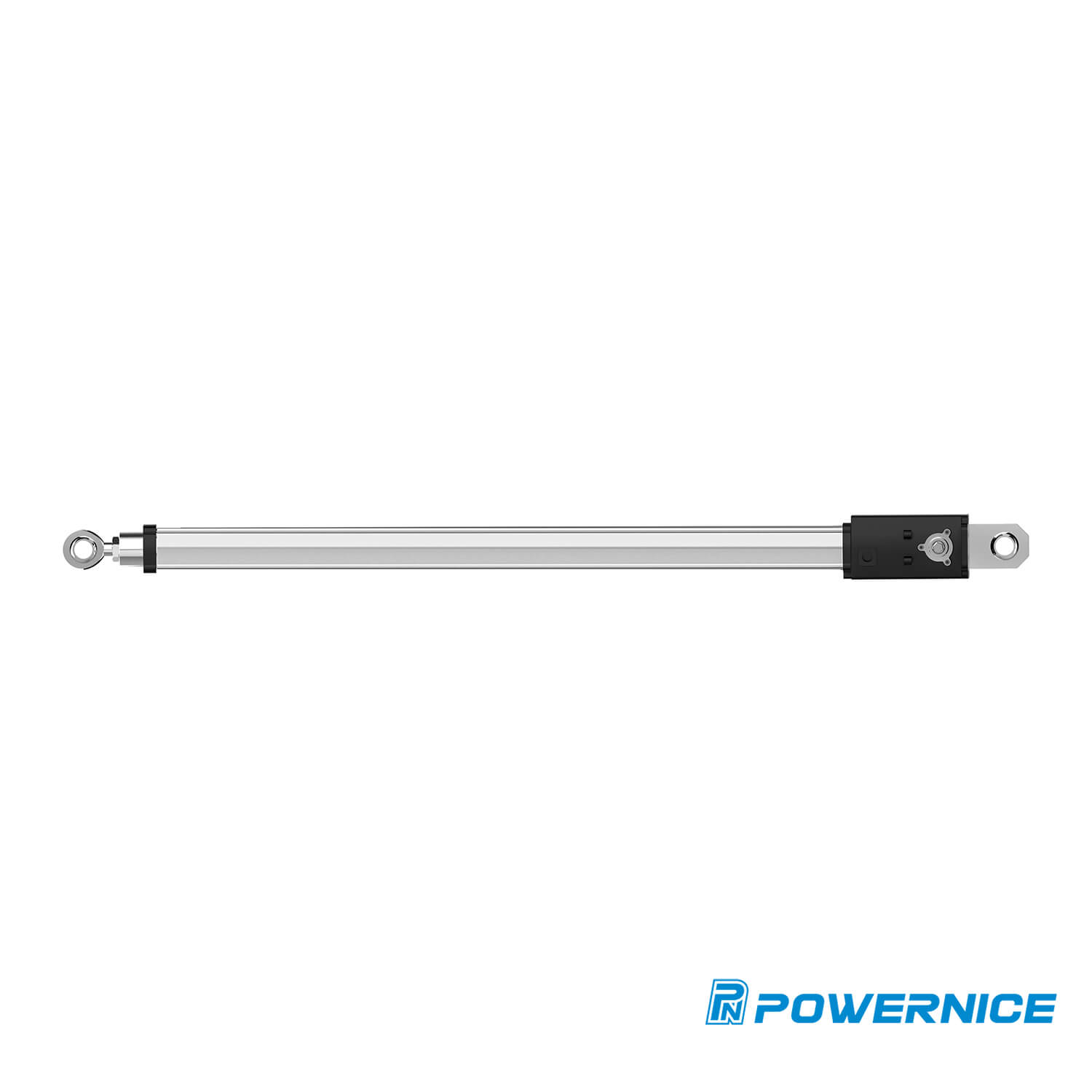
Table of Contents
Before calculating actuator force, identify the loads acting on the tracker and the conditions the system must withstand. Do not use panel weight alone to determine the actuator rating.
Static loads include the weight of the PV modules, mounting rails, torque tube, brackets, and other supported components. Gravity creates a rotational moment when the combined center of gravity does not align with the pivot axis.
The relevant factor is not just total mass. It is also the distance and direction between the center of gravity and the pivot. A balanced array may require relatively little actuator force to counter gravity, while an unbalanced design can create a larger moment.
Convert mass to weight when necessary:
Weight = Mass × Gravitational Acceleration
Use consistent units throughout the calculation. For example, if mass is in kilograms, weight is in newtons when gravitational acceleration is expressed in meters per second squared.
Wind can create uplift, downward pressure, and torsional effects on a solar array. The resulting forces depend on wind speed, panel orientation, array geometry, exposure, and applicable design requirements.
Snow can add weight and create uneven loading, depending on local conditions and the array's tilt. Other site-specific conditions may also affect the structural load case.
Use the applicable local building codes, project design criteria, and engineering load combinations to establish the required loads. Do not treat a single wind speed or snow-load value as suitable for every installation.
The actuator force calculation should reflect the relevant design cases, including the required tracking positions and the designated wind-stow position.
Torque is the rotational effect of a force around a pivot. It depends on the force's magnitude, direction, and distance from the pivot.
For a force acting at a distance, the basic relationship is:
Torque = Force × Perpendicular Distance
In vector form, the magnitude is:
Torque = r × F × sin(θ)
Where:
Torque is the moment around the pivot, measured in newton-meters (N·m).
F is the applied force, measured in newtons (N).
r is the distance from the pivot to the force application point, measured in meters (m).
θ is the angle between the position vector and the force direction.
Calculate the moment created by each relevant load using its own direction and point of application. Then combine the moments according to the applicable design load case.
Do not simply add all loads as positive values. Forces acting in opposite directions may create moments that oppose one another, while other loads may increase the total moment.
For a detailed design, account for the array's geometry and orientation throughout the required operating range.
The actuator's mounting geometry determines how effectively its linear force rotates the tracker.
The effective moment arm is the perpendicular distance from the pivot to the actuator's line of action. It changes as the actuator and tracker move through different angles.
For an idealized arrangement:
Actuator Force = Required Torque ÷ Effective Moment Arm
For example, if a design requires 1,000 N·m of torque and the actuator's effective moment arm is 0.25 m at a particular position, the idealized actuator force at that position is:
1,000 N·m ÷ 0.25 m = 4,000 N
This example illustrates the calculation only. It is not a recommended actuator rating and does not include all design loads, friction, structural effects, or required design margins.
If the effective moment arm becomes smaller, the actuator must generate more force to produce the same torque. A poor mounting angle can therefore increase the required force significantly.
Do not calculate actuator force at only one tracker angle. The effective moment arm changes with the relative positions of the pivot, actuator mounts, and moving structure.
Evaluate the geometry at multiple positions, including:
Minimum actuator extension
Intermediate positions
Maximum actuator extension
Required operating-angle limits
The designated wind-stow position
For each position, calculate the required moment and the corresponding actuator force. Identify the governing design case rather than selecting an actuator based on an average force.
Also confirm that the actuator's stroke is sufficient to achieve the required tracking angles without interference or mechanical overtravel.
For projects with complex mounting geometry, use a CAD model or a validated actuator sizing tool to check the full motion range.
The calculated force is only one part of actuator selection. The final specification must reflect the project's applicable engineering requirements and the manufacturer's rated performance.
Do not assume that a single safety factor applies to every solar tracker. The appropriate margin depends on the governing design code, load combinations, uncertainties, duty conditions, and the design limits of the complete mechanism.
Verify the following:
The required actuator force under each governing load case
The manufacturer's rated push and pull forces, where applicable
The required static holding capacity
The capacity of mounting brackets, pins, bolts, and supporting structures
Any relevant limitations on load direction, speed, stroke, and operating temperature
The actuator must not be treated as the only load-bearing component. The entire force path, from the panel structure through the mounting hardware and actuator to the supporting frame, must be checked.
Different tracker designs transfer loads through different mechanisms. The actuator sizing method must reflect the actual system architecture.
A single-axis tracker rotates the array around one main axis. Its actuator force depends on the tracker geometry, gravity imbalance, bearing resistance, wind loads, and the design of the drive linkage.
Some systems use mechanical linkages or multiple actuators. In these cases, do not assume the total load is shared equally unless the design and control arrangement support that assumption.
The required stow position is also important. Evaluate the loads and holding requirements at the specified stow angle, rather than assuming that a flat position always produces the lowest load.
A dual-axis tracker moves the array around two axes, often using separate mechanisms for elevation and azimuth.
The elevation mechanism may need to counter gravity and wind-induced moments. The azimuth mechanism must be sized for its own rotational loads, drive geometry, and wind conditions.
Evaluate each axis separately, then verify how the combined system behaves under the required operating and stow conditions. The two axes should not be assigned identical actuator requirements without a design-based reason.
Correct force calculations cannot compensate for unsuitable mounting geometry or undersized hardware.
Check the following before confirming the actuator specification:
Mounting positions: Confirm the pivot and actuator attachment coordinates across the full movement range.
Stroke length: Ensure the actuator can reach all required positions without bottoming out or exceeding its mechanical limits.
Clearance: Check for interference between the actuator, frame, wiring, and adjacent components.
Brackets and pins: Verify their strength against the calculated loads, including relevant shear, bending, bearing, and fatigue effects.
Alignment: Avoid unintended side loads that exceed the actuator manufacturer's limits.
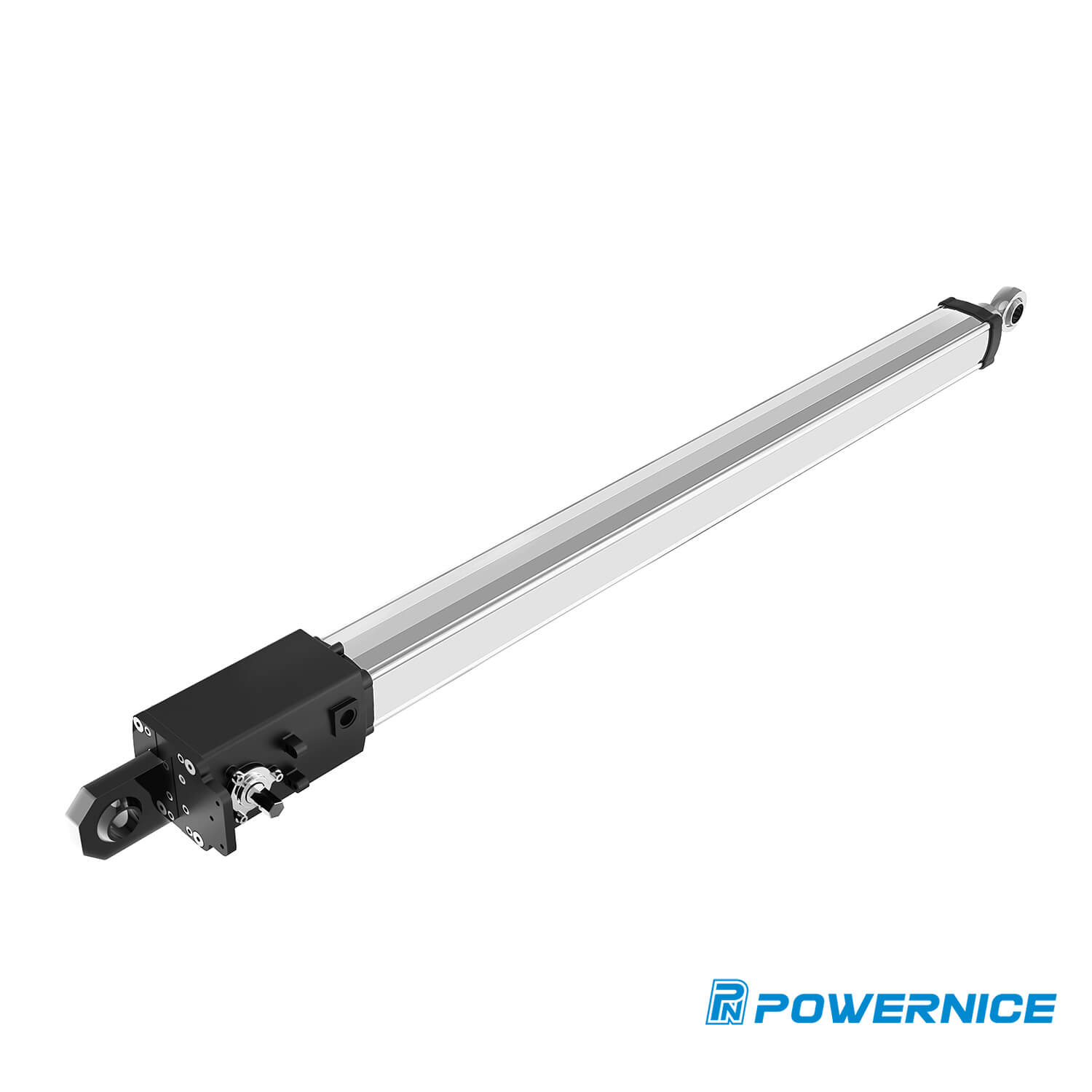
The actuator and its mounting hardware should be evaluated as one mechanical system. A strong actuator can still be compromised by a weak bracket, poor alignment, or an unsuitable connection pin.
The force needed to move a tracker is not necessarily the same as the force needed to hold it in place.
Dynamic force relates to the actuator's ability to move the mechanism under the specified operating conditions. Static holding capacity relates to its ability to resist an applied load while stationary.
Confirm both requirements with the manufacturer. Do not assume the actuator can safely hold a severe wind load simply because its rated moving force appears sufficient.
Back-driving occurs when an external load drives the actuator mechanism in the reverse direction. Whether this can happen depends on the screw mechanism, gearing, friction, load, and other design characteristics.
Do not assume that a particular screw type guarantees self-locking under all conditions. Verify the manufacturer's back-driving and holding specifications. Where the design requires additional restraint, evaluate an appropriate brake or independent locking mechanism.
Solar trackers operate outdoors, so dust, rain, temperature variation, and other environmental factors should be considered.
Choose the actuator's ingress protection rating based on the actual exposure and installation conditions. Also verify the specified operating-temperature range, corrosion protection, cable and connector protection, and maintenance requirements.
An IP rating alone does not confirm that an actuator is suitable for every outdoor environment.
After completing the load and geometry analysis, compare the calculated requirements with the manufacturer's product specifications.
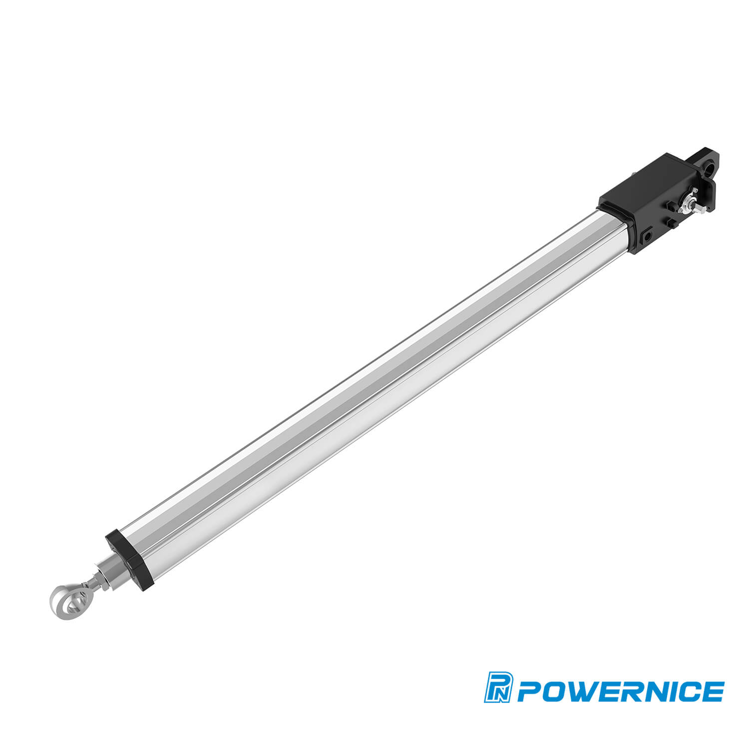
Powernice offers a range of solar tracker linear actuators. For example, the PA13 solar tracker linear actuator is listed with a maximum thrust of 51,000 N. This is a product-specific published value, not a universal requirement for solar trackers.
When reviewing a candidate model, confirm:
Rated force and applicable load direction
Stroke and installation dimensions
Operating speed and duty conditions
Holding or braking capability
Environmental protection and temperature limits
Feedback and control options, if needed
Compatibility with the tracker structure and mounting hardware
If position feedback is required, review options such as a solar tracker actuator with an encoder. Confirm the actual sensor and control specifications for the selected model.
For project-specific selection, provide the supplier with the tracker geometry, load cases, stroke, operating range, stow requirements, and environmental conditions.
Calculating linear actuator force for a solar tracker requires more than dividing panel weight by a distance. Engineers must establish the relevant load cases, calculate moments around the pivot, determine the actuator's effective moment arm, and check the force requirement throughout the stroke.
Before finalizing a model:
Establish the design loads using the applicable project requirements.
Calculate the required moments and actuator forces at critical positions.
Verify stroke, mounting geometry, and hardware capacity.
Confirm dynamic force, static holding capacity, back-driving behavior, and environmental suitability.
Compare the results with manufacturer specifications and obtain engineering confirmation where required.
To discuss your project requirements, contact Powernice with your tracker layout, load data, and required movement range.
Calculate the moments created by the relevant loads around the pivot. Divide the required moment by the actuator's effective perpendicular moment arm at each critical position, then evaluate the governing force requirement and applicable design margins.
Consider the weight of the panels and supporting structure, gravity imbalance, wind loads, snow loads where applicable, friction, and other project-specific loads. Use the applicable engineering load cases rather than panel weight alone.
The actuator produces torque through its effective moment arm. A shorter perpendicular distance or an unfavorable mounting angle requires more actuator force to generate the same torque.
No. Moving force describes the actuator's ability to move the mechanism under specified conditions. Holding capacity describes its ability to resist external loads while stationary. Both must be verified for the application.
Compare the calculated force and holding requirements with the manufacturer's ratings. Also check stroke, mounting dimensions, operating speed, duty conditions, environmental protection, back-driving behavior, and control requirements.
