

Views: 0 Author: Site Editor Publish Time: 2026-10-13 Origin: Site


Solar tracker actuators help photovoltaic panels follow the sun throughout the day. When an actuator stops, moves unevenly, or fails to hold its position, the tracking system may lose accuracy and require unplanned maintenance.
Common solar tracker actuator problems include power supply faults, damaged wiring, mechanical binding, water ingress, worn drive components, and position feedback errors. However, an actuator that does not move is not always defective. The cause may be in the controller, sensors, mounting structure, or power supply.
This guide explains how to identify common symptoms, troubleshoot potential causes, and decide whether repair or replacement is the better option. It also covers the specifications to review when sourcing a replacement solar tracker linear actuator.
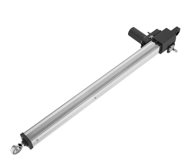
Table of Contents
A malfunctioning actuator can interrupt panel movement, prevent the tracker from reaching its commanded position, or affect the system's ability to enter its designated stow position. The impact depends on the tracker design, operating conditions, fault duration, and whether backup controls are available.
Before replacing an actuator, establish a diagnostic sequence:
Review controller alarms and operating records, if available.
Check the power supply, fuses, connectors, and cable condition.
Inspect the actuator mounts and tracker structure for binding or misalignment.
Compare the actuator's behavior with the manufacturer's troubleshooting instructions.
Confirm whether the fault is in the actuator, controller, sensor, or mechanical structure.
Do not disconnect mounting pins or attempt to move a loaded tracker before securing the array. Follow the site's lockout procedures and the manufacturer's safety instructions. Wind-related stow and structural safety functions should be handled by qualified personnel.
A controller that clicks while the actuator remains stationary may indicate a weak power supply, a blown fuse, loose or corroded wiring, a faulty relay, or a failed motor. The sound alone does not confirm which component has failed.
Use a multimeter to check the supply voltage at the appropriate test points and compare the reading with the actuator's rated input. Where appropriate, check voltage under operating load because a connection may show normal voltage without load but drop when current is drawn.
If the actuator moves in one direction but not the other, inspect the controller outputs, directional wiring, limit-switch circuit, and any position or sensor signals used by the system. Follow the wiring diagram for the specific tracker model. Not every tracker uses the same sensors or control logic.
Disconnect power before inspecting wiring or opening electrical enclosures. Electrical testing should be performed by qualified personnel using the correct procedures and protective equipment.
Mechanical problems may cause slow movement, jerking, unusual noise, repeated stalling, or visible deformation. Possible causes include misaligned mounts, excessive friction at pivots, a bent extension rod, damaged gears, or a worn internal drive mechanism.
Inspect the actuator mounting points, clevis connections, brackets, and tracker structure for looseness, deformation, corrosion, and signs of side-loading. Confirm that the actuator follows the intended line of motion throughout the operating range.
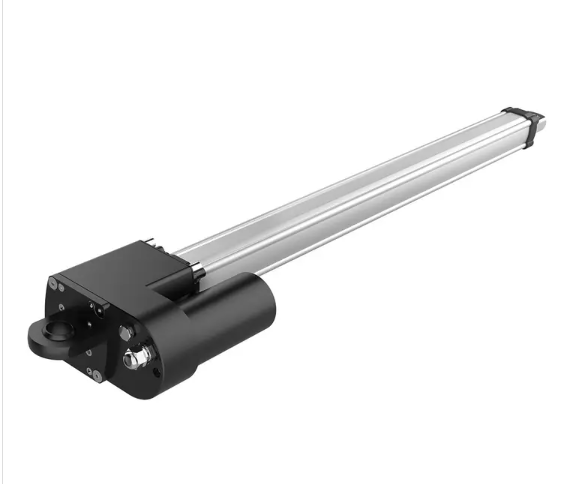
Do not remove pins or run the actuator unloaded until the array and actuator are safely supported and the manufacturer's procedure allows it. If the actuator continues to bind or make grinding noises after external alignment issues have been ruled out, internal damage may require professional inspection or replacement.
Moisture can enter an actuator through damaged seals, loose cable connections, cracked housings, or installation conditions outside the unit's specified protection limits. Water and corrosion may damage electrical connections, bearings, or internal drive components.
Troubleshooting steps:
Inspect the housing, cable entries, seals, and exposed shaft for visible damage.
Check connectors and cables for corrosion or moisture.
Follow the manufacturer's procedure for evaluating water ingress.
Replace the actuator if the damage is extensive or the unit cannot be restored to its specified protection level.
Choose an actuator with an ingress protection rating suitable for the installation environment. IP ratings describe performance under specified test conditions; they do not guarantee protection in every exposure scenario. Confirm whether the rating applies to the installed configuration and relevant moving seals.
See PowerNice's solar tracker linear actuator products for examples of products designed for solar tracking applications.
A damaged drive mechanism may produce grinding noises, irregular movement, or a failure to maintain the commanded position. Excessive loading, shock loads, misalignment, repeated stalling, or wear may contribute to internal damage.
Wind loads require particular attention. The appropriate actuator and tracker design depend on the panel area, tracker geometry, site wind conditions, structural loads, and the system's stow strategy. A thrust or static load figure alone is not enough to confirm that the complete tracker is safe.
Troubleshooting steps:
Check for external binding and mounting misalignment.
Review controller records for repeated stalls or overload indications.
Inspect the actuator according to the manufacturer's service procedure.
Replace a unit with severe internal damage or unreliable holding performance.
Do not assume that every actuator uses a self-locking screw or an internal brake. Confirm the actual holding mechanism and the required operating conditions in the product documentation.
An actuator motor may overheat if it operates beyond its rated duty cycle, encounters excessive mechanical resistance, receives an unsuitable power supply, or repeatedly stalls. A blown fuse may be a symptom of the underlying problem rather than the root cause.
Troubleshooting steps:
Check for binding in the tracker pivots and mounting geometry.
Verify the power supply and wiring against the actuator specifications.
Review the duty cycle and operating frequency.
Check for repeated stalls, abnormal current draw, or thermal protection events where monitoring is available.
Replace or service the motor according to the manufacturer's guidance.
Correcting the mechanical or electrical cause is important. Replacing a motor without resolving the underlying problem may lead to another failure.
A limit switch or position feedback fault may cause an actuator to stop too early, fail to complete a movement, or report an incorrect position. The actual cause could be a damaged switch, loose wiring, sensor failure, incorrect calibration, or a controller issue.
Position feedback systems vary. Some actuators use limit switches, while others may use Hall sensors, potentiometers, or encoders. The correct troubleshooting method depends on the actuator and controller configuration.
Troubleshooting steps:
Review fault codes and position data where available.
Inspect the relevant connectors and wiring.
Check limit-switch operation or sensor signals using the manufacturer's procedure.
Verify that the feedback type and calibration match the controller requirements.
Replace faulty components only after confirming the cause.
Do not bypass safety limits or change travel settings without the approved procedure. Incorrect settings can cause overtravel or mechanical damage.
A tracker may fail to move even when the actuator itself is functional. Possible causes include controller faults, missing sensor signals, communication interruptions, incorrect configuration, or a problem with the wind-stow command.
Not every tracker uses optical sensors, anemometers, or the same communication protocol. Begin with the system wiring diagram and controller documentation rather than assuming a particular sensor is installed.
Troubleshooting steps:
Review alarms, event logs, and communication status.
Check the controller's power supply and relevant output signals.
Inspect sensor connections and cables for damage or moisture.
Confirm the controller configuration and feedback compatibility.
Test emergency stow functions only under the approved site procedure.
For broader system context, see PowerNice's solar tracking solutions.
Repair may be appropriate when the fault is isolated to an accessible external component and the manufacturer supports replacement or service. Examples may include a damaged connector, external cable, fuse, or replaceable sensor.
Replacement or manufacturer-level service is usually more appropriate when the actuator has a bent rod, cracked housing, extensive water damage, severe internal gear damage, or unreliable holding performance. Internal repairs should only be attempted when the design is serviceable and suitable parts and procedures are available.
Condition | Recommended action | Reason |
|---|---|---|
Loose or corroded external connector | Inspect and repair if approved | The fault may be outside the actuator |
Damaged cable or fuse | Repair or replace after finding the cause | A repeated fuse failure may indicate a deeper fault |
Misaligned mount or binding pivot | Correct the structural issue | Replacing the actuator alone may not solve the problem |
Bent rod or cracked housing | Replace or obtain manufacturer assessment | Structural damage may affect alignment and sealing |
Extensive water or internal gear damage | Manufacturer assessment or replacement | Reliability may not be restored by a minor repair |
Position feedback or controller fault | Diagnose the complete control circuit | The actuator may still be functional |
Compare the cost of parts and labor with the expected reliability after repair, downtime, and the consequences of another failure. Do not classify an actuator as under-specified solely because it has failed once; verify the load calculations, installation geometry, control settings, and environmental conditions first.
Selecting a replacement requires more than matching the old actuator's physical dimensions. Confirm the following details with the system designer or actuator supplier.
Review the required dynamic thrust, holding force, loading direction, expected duty cycle, and any relevant shock or wind-load cases. The complete tracker structure, drive arrangement, and stow strategy must be evaluated together.
Do not apply a universal safety factor without a design basis. The appropriate margin depends on the applicable engineering requirements and project conditions.
Confirm the required stroke, retracted length, extended length, mounting orientation, and pin-to-pin dimensions. Check clearances throughout the full movement range, not only at the starting position.
Choose a protection rating suitable for rain, dust, temperature variation, humidity, and other site conditions. Verify the specified operating temperature range and whether the protection rating applies to moving seals and cable entries in the installed configuration.
Match the input voltage, current requirements, wiring, control signals, and feedback type to the existing controller. If the project uses a Hall sensor, potentiometer, encoder, or limit switches, confirm compatibility before ordering.
Explore PowerNice's solar tracker linear actuator range and contact the supplier with the application requirements for model selection.
A consistent inspection plan can help identify wear and installation issues before they cause extended downtime. Follow the equipment manufacturer's maintenance schedule and the site's safety procedures.
Visual inspection: Check the housing, shaft, seals, cables, and connectors for visible damage or corrosion.
Mounting inspection: Check brackets, fasteners, clevis connections, and pivot points for looseness or deformation.
Movement check: Review unusual noise, jerking, stalling, or changes in operating time.
Electrical inspection: Check relevant connections, controller alarms, and power readings using approved procedures.
Protection check: Inspect cable entries and seals for damage that could allow moisture ingress.
Control and stow testing: Verify position feedback and emergency stow functions according to the manufacturer's approved test procedure.
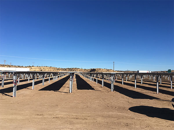
Solar tracker actuator problems can originate in the power supply, controller, sensors, mounting structure, or actuator itself. A structured diagnostic process helps avoid unnecessary replacement and identifies the cause of recurring failures.
Before sourcing a replacement, verify the required thrust and holding performance, stroke length, installation dimensions, environmental protection, power supply, and feedback compatibility. These checks help ensure the new actuator suits the tracker design and site conditions.
For product options, visit PowerNice's solar tracker linear actuator page. Provide the tracker configuration, load requirements, stroke, input voltage, and control interface when requesting a recommendation.
Possible causes include a weak power supply, damaged wiring, a blown fuse, a faulty relay, a motor fault, or mechanical binding. Check the supply and controller according to the manufacturer's troubleshooting procedure before replacing the actuator.
Possible causes include a directional output fault, a limit-switch issue, incorrect controller settings, or a position feedback problem. Check the wiring diagram and controller alarms to identify the cause.
It depends on the extent of the damage and whether the actuator is serviceable. Moisture-related corrosion or internal damage may require manufacturer assessment or replacement. Follow the approved service procedure rather than using a generic lubricant or resealing method.
Confirm the required thrust and holding performance, stroke length, mounting dimensions, input voltage, feedback type, duty cycle, and environmental protection. Also review the tracker's structural loads and stow requirements.
Inspect mounting alignment, cables, connectors, seals, and pivot points regularly. Monitor abnormal noise, stalling, and controller alarms, and test tracking and stow functions according to the manufacturer's maintenance instructions.
